


Steps and methods for debugging laser optical system (1)
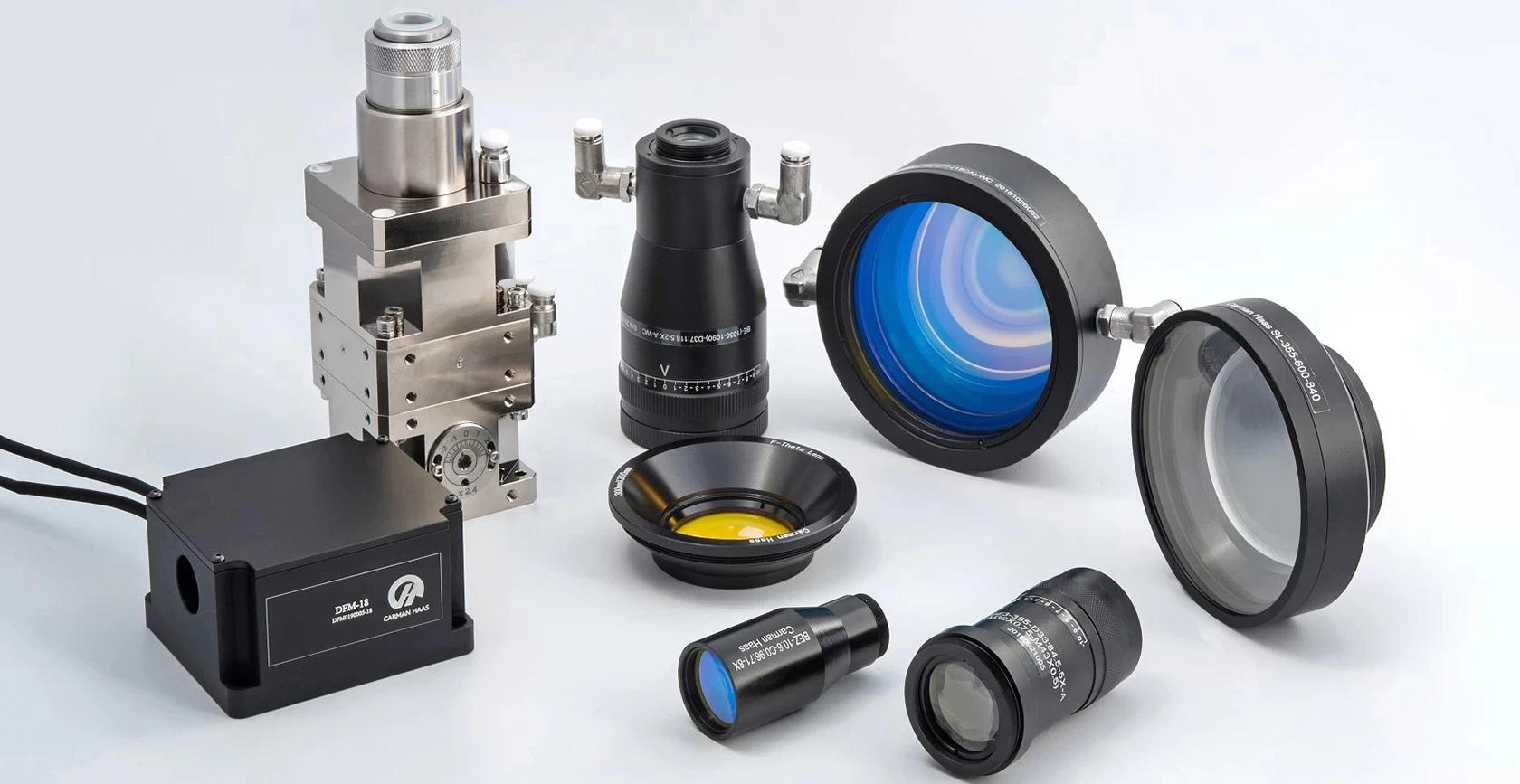
1. The first thing is to fix the optical scanning galvanometer device. The scanning galvanometer device and Y scanning galvanometer should be placed straight, and the X scanning galvanometer should be placed horizontally. When the device is installed, it can be investigated from the side hole of the scanning head to make X, The orientation of the Y lens is orthogonal, and the coating surface of the lens faces the historical light direction; visually, the Y galvanometer lens and the X galvanometer lens are aligned in the middle of the survey holes, that is, the height is the same, and the horizontal alignment.
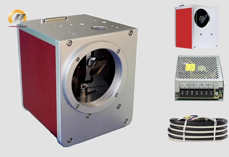
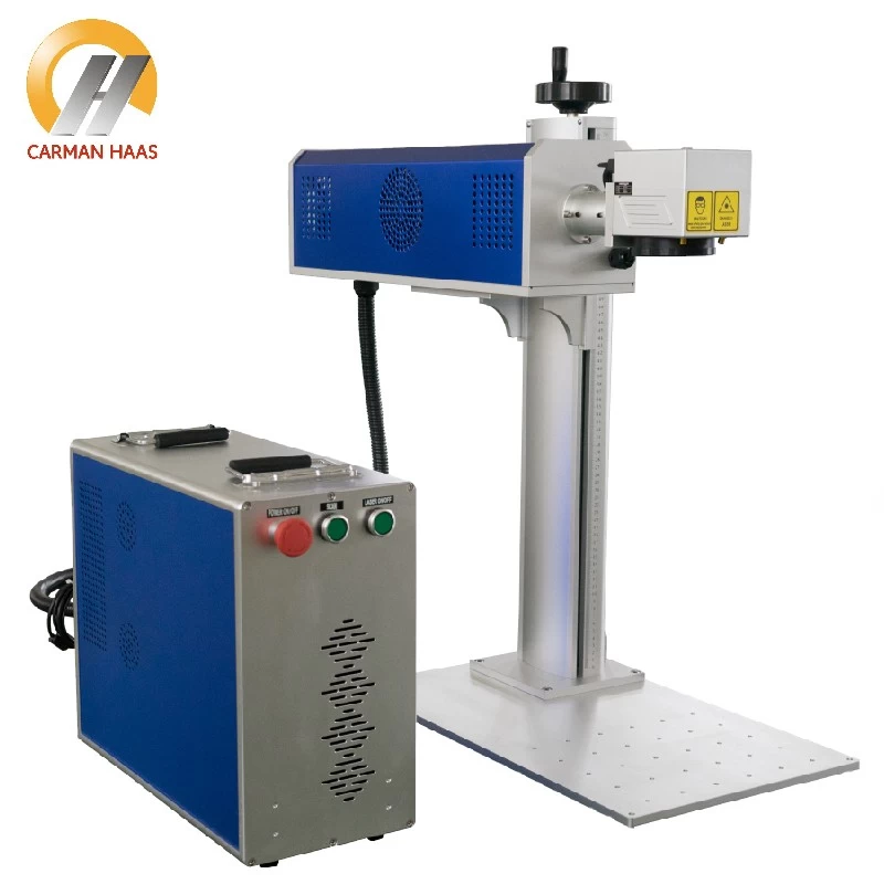
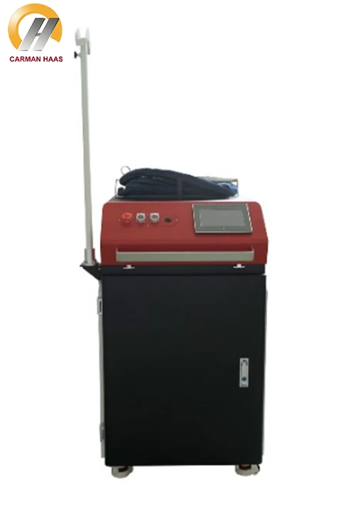
Galvo Fiber Laser Manufacturer China
2. Secondly, fix the red light diode laser, and then turn on the power to adjust the red light to the best condition (beam expander and field lens cannot be installed at this moment). Adjust the optical bench so that the red light spot passes through the middle of the laser output hole on the front panel, and directly hits the middle of the Y-axis galvanometer. Check the holes on both sides of the galvanometer. The red dot should be between the Y galvanometer lens and the X vibration. The middle of the mirror lens.
3. Rotate the Y galvanometer and X galvanometer, and keep the axial direction not moving; make the red light hit the galvanometer or directly under the worktable, and fix the galvanometer tightly.
4. When installing (concentrating cavity) or semiconductor side pump module, let the red light from both ends of the Nd:YAG crystal rod be in the middle of the rod sleeve, that is, the middle of the laser rod. This step is the most important. Straighten other components to supply the light source.
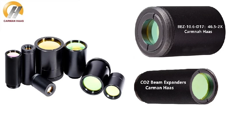
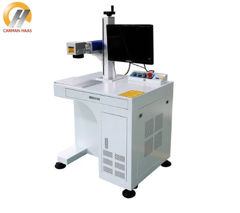
Fixed Magnification Beam Expanders manufacturer
5. Install the total mirror, output mirror, beam expander, acousto-optic Q switch, the same must enter the middle out, and the coating surface of the total mirror and the output mirror face the condenser cavity, and the red light or laser must be directed straight On the lens.
6. According to the principle of optical reflection, the red light shines on the total mirror, there must be a reflected light spot. Adjust the tilt and side turn knobs of the total mirror, so that the reflected light spot comes back along the original path, and is connected to the output end of the diode laser. The light spots coincide.
7. Adjust the Q switch and the tilt and side rotation knobs of the output mirror to make the reflection point coincide with the output light point of the diode laser (red light).
8. Finally, check whether the red light from the output mirror overlaps, if not, adjust it to a point from the beginning. At this time, the optical path of the laser machine is completely debugged.